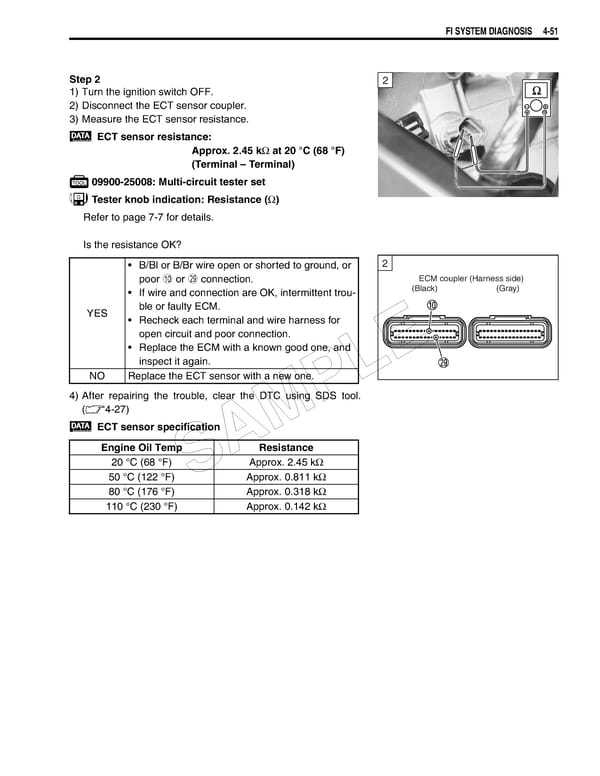
FI SYSTEM DIAGNOSIS 4-51 Step 2 2 1) Turn the ignition switch OFF. 2) Disconnect the ECT sensor coupler. 3) Measure the ECT sensor resistance. ECT sensor resistance: Approx. 2.45 kΩ at 20 °C (68 °F) (Terminal – Terminal) 09900-25008: Multi-circuit tester set Tester knob indication: Resistance (Ω) Refer to page 7-7 for details. Is the resistance OK? • B/Bl or B/Br wire open or shorted to ground, or 2 poor 0 or S connection. ECM coupler (Harness side) • If wire and connection are OK, intermittent trou- (Black) (Gray) YES ble or faulty ECM. • Recheck each terminal and wire harness for open circuit and poor connection. • Replace the ECM with a known good one, and E inspect it again. NO Replace the ECT sensor with a new one. L 4) After repairing the trouble, clear the DTC using SDS tool. (4-27) P ECT sensor specification M Engine Oil Temp Resistance A 20 °C (68 °F) S Approx. 2.45 kΩ 50 °C (122 °F) Approx. 0.811 kΩ 80 °C (176 °F) Approx. 0.318 kΩ 110 °C (230 °F) Approx. 0.142 kΩ
 Suzuki GSXR 1000 K5 K6 Page 210 Page 212