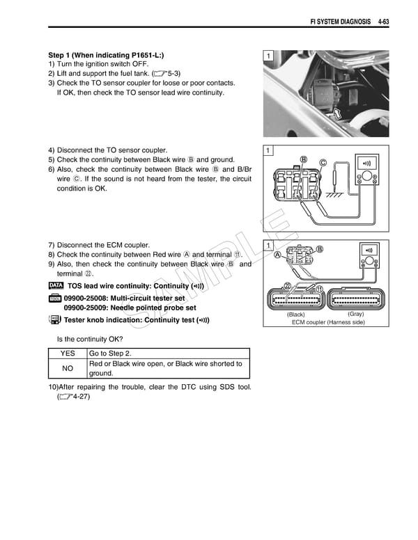
FI SYSTEM DIAGNOSIS 4-63 Step 1 (When indicating P1651-L:) 1 1) Turn the ignition switch OFF. 2) Lift and support the fuel tank. (5-3) 3) Check the TO sensor coupler for loose or poor contacts. If OK, then check the TO sensor lead wire continuity. 4) Disconnect the TO sensor coupler. 1 5) Check the continuity between Black wire B and ground. ! 6) Also, check the continuity between Black wire B and B/Br wire C. If the sound is not heard from the tester, the circuit condition is OK. 7) Disconnect the ECM coupler. 1 E 8) Check the continuity between Red wire A and terminal A. L 9) Also, then check the continuity between Black wire B and terminal L. P TOS lead wire continuity: Continuity () 09900-25008: Multi-circuit tester set M 09900-25009: Needle pointed probe set A (Black) (Gray) Tester knob indication: Continuity test () ECM coupler (Harness side) S Is the continuity OK? YES Go to Step 2. NO Red or Black wire open, or Black wire shorted to ground. 10)After repairing the trouble, clear the DTC using SDS tool. (4-27)
 Suzuki GSXR 1000 K5 K6 Page 222 Page 224