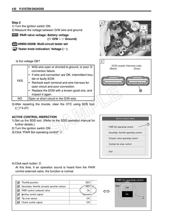
4-92 FI SYSTEM DIAGNOSIS Step 2 2 1)Turn the ignition switch ON. V 2)Measure the voltage between O/W wire and ground. PAIR valve voltage: Battery voltage (+ O/W – - Ground) 09900-25008: Multi-circuit tester set Tester knob indication: Voltage () Is the voltage OK? 2 • W/G wire open or shorted to ground, or poor t ECM coupler (Harness side) connection failure. (Black) (Gray) • If wire and connection are OK, intermittent trou- YES ble or faulty ECM. • Recheck each terminal and wire harness for open circuit and poor connection. • Replace the ECM with a known good one, and inspect it again. NO Open or short circuit in the O/W wire. E 3)After repairing the trouble, clear the DTC using SDS tool. L (4-27) P ACTIVE CONTROL INSPECTION 1)Set up the SDS tool. (Refer to the SDS operation manual for further details.) M 2)Turn the ignition switch ON. A 3)Click “PAIR Sol operating control” 1. S 4)Click each button 2. At this time, if an operation sound is heard from the PAIR control solenoid valve, the function is normal.
 Suzuki GSXR 1000 K5 K6 Page 251 Page 253