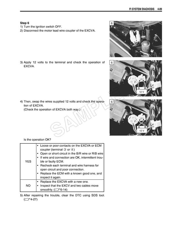
FI SYSTEM DIAGNOSIS 4-89 Step 6 6 1) Turn the ignition switch OFF. 2) Disconnect the motor lead wire coupler of the EXCVA. 3) Apply 12 volts to the terminal and check the operation of 6 EXCVA. 12 V 4) Then, swap the wires supplied 12 volts and check the opera- 6 E tion of EXCVA. (Check the operation of EXCVA both way.) L P M A 12 V Is the operation OK? S • Loose or poor contacts on the EXCVA or ECM coupler (terminal 3 or 4) • Open or short circuit in the B/R wire or R/B wire • If wire and connection are OK, intermittent trou- YES ble or faulty ECM. • Recheck each terminal and wire harness for open circuit and poor connection. • Replace the ECM with a known good one, and inspect it again. • Replace the EXCVA with a new one. NO • Inspect that the EXCV and two cables move smoothly. (6-14) 5) After repairing the trouble, clear the DTC using SDS tool. (4-27)
 Suzuki GSXR 1000 K5 K6 Page 248 Page 250