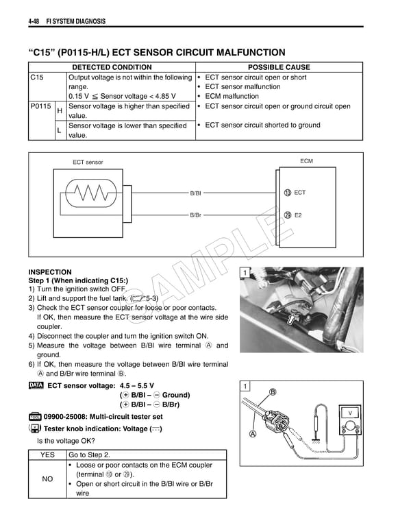
4-48 FI SYSTEM DIAGNOSIS “C15” (P0115-H/L) ECT SENSOR CIRCUIT MALFUNCTION DETECTED CONDITION POSSIBLE CAUSE C15 Output voltage is not within the following • ECT sensor circuit open or short range. • ECT sensor malfunction 0.15 V Sensor voltage < 4.85 V • ECM malfunction P0115 H Sensor voltage is higher than specified • ECT sensor circuit open or ground circuit open value. L Sensor voltage is lower than specified • ECT sensor circuit shorted to ground value. ECT sensor ECM B/BI ECT B/Br E2 E L INSPECTION 1 Step 1 (When indicating C15:) P 1) Turn the ignition switch OFF. M 2) Lift and support the fuel tank. (5-3) 3) Check the ECT sensor coupler for loose or poor contacts. A If OK, then measure the ECT sensor voltage at the wire side coupler. S 4) Disconnect the coupler and turn the ignition switch ON. 5) Measure the voltage between B/Bl wire terminal A and ground. 6) If OK, then measure the voltage between B/Bl wire terminal A and B/Br wire terminal B. ECT sensor voltage: 4.5 – 5.5 V 1 (+ B/Bl – - Ground) (+ B/Bl – - B/Br) 09900-25008: Multi-circuit tester set V Tester knob indication: Voltage () Is the voltage OK? YES Go to Step 2. • Loose or poor contacts on the ECM coupler NO (terminal 0 or S). • Open or short circuit in the B/Bl wire or B/Br wire
 Suzuki GSXR 1000 K5 K6 Page 207 Page 209