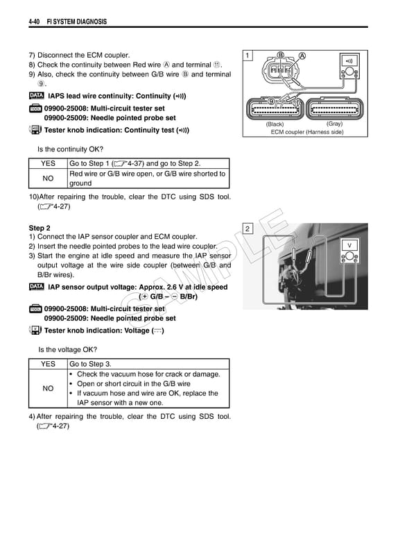
4-40 FI SYSTEM DIAGNOSIS 7) Disconnect the ECM coupler. 1 ! 8) Check the continuity between Red wire A and terminal A. 9) Also, check the continuity between G/B wire B and terminal 9. IAPS lead wire continuity: Continuity () 09900-25008: Multi-circuit tester set 09900-25009: Needle pointed probe set Tester knob indication: Continuity test () (Black) (Gray) ECM coupler (Harness side) Is the continuity OK? YES Go to Step 1 (4-37) and go to Step 2. NO Red wire or G/B wire open, or G/B wire shorted to ground 10)After repairing the trouble, clear the DTC using SDS tool. (4-27) Step 2 2 1) Connect the IAP sensor coupler and ECM coupler. 2) Insert the needle pointed probes to the lead wire coupler. E V 3) Start the engine at idle speed and measure the IAP sensor L output voltage at the wire side coupler (between G/B and B/Br wires). P IAP sensor output voltage: Approx. 2.6 V at idle speed (+ G/B – - B/Br) M 09900-25008: Multi-circuit tester set A 09900-25009: Needle pointed probe set S Tester knob indication: Voltage () Is the voltage OK? YES Go to Step 3. • Check the vacuum hose for crack or damage. NO • Open or short circuit in the G/B wire • If vacuum hose and wire are OK, replace the IAP sensor with a new one. 4)After repairing the trouble, clear the DTC using SDS tool. (4-27)
 Suzuki GSXR 1000 K5 K6 Page 199 Page 201