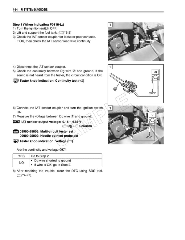
4-54 FI SYSTEM DIAGNOSIS Step 1 (When indicating P0110-L:) 1 1) Turn the ignition switch OFF. 2) Lift and support the fuel tank. (5-3) 3) Check the IAT sensor coupler for loose or poor contacts. If OK, then check the IAT sensor lead wire continuity. 4) Disconnect the IAT sensor coupler. 1 5) Check the continuity between Dg wire A and ground. If the sound is not heard from the tester, the circuit condition is OK. Tester knob indication: Continuity test () 6) Connect the IAT sensor coupler and turn the ignition switch 1 E ON. 7) Measure the voltage between Dg wire A and ground. L V IAT sensor output voltage: 0.15 – 4.85 V P (+ Dg – - Ground) 09900-25008: Multi-circuit tester set M 09900-25009: Needle pointed probe set A Tester knob indication: Voltage () S Are the continuity and voltage OK? YES Go to Step 2. NO • Dg wire shorted to ground • If wire is OK, go to Step 2. 8) After repairing the trouble, clear the DTC using SDS tool. (4-27)
 Suzuki GSXR 1000 K5 K6 Page 213 Page 215