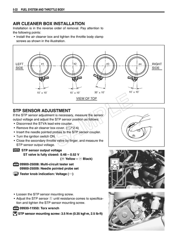
5-22 FUEL SYSTEM AND THROTTLE BODY AIR CLEANER BOX INSTALLATION Installation is in the reverse order of removal. Pay attention to the following points: • Install the air cleaner box and tighten the throttle body clamp screws as shown in the illustration. LEFT #1 #2 #3 #4 RIGHT SIDE SIDE 10˚ ± 10˚ 10˚ ± 10˚ 30˚ ± 10˚ 10˚ ± 10˚ VIEW OF TOP E STP SENSOR ADJUSTMENT If the STP sensor adjustment is necessary, measure the sensor L output voltage and adjust the STP sensor position as follows: • Disconnect the STVA lead wire coupler. P • Remove the air cleaner box cover. (2-4) • Insert the needle pointed probes to the STP sensor coupler. M • Turn the ignition switch ON. A • Close the secondary throttle valve by finger, and measure the STP sensor output voltage. S STP sensor output voltage ST valve is fully closed: 0.48 – 0.52 V (+ Yellow – - Black) 09900-25008: Multi-circuit tester set V 09900-25009: Needle pointed probe set Tester knob indication: Voltage () • Loosen the STP sensor mounting screw. • Adjust the STP sensor 1 until resistance comes to specifica- tion and tighten the STP sensor mounting screw. 09930-11950: Torx wrench STP sensor mounting screw: 3.5 N·m (0.35 kgf-m, 2.5 lb-ft)
 Suzuki GSXR 1000 K5 K6 Page 278 Page 280