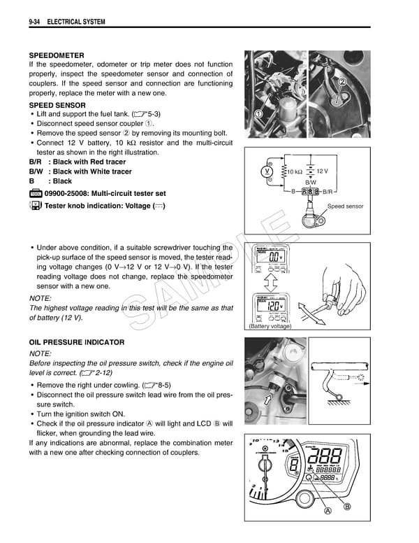
9-34 ELECTRICAL SYSTEM SPEEDOMETER If the speedometer, odometer or trip meter does not function properly, inspect the speedometer sensor and connection of couplers. If the speed sensor and connection are functioning properly, replace the meter with a new one. SPEED SENSOR • Lift and support the fuel tank. (5-3) • Disconnect speed sensor coupler 1. • Remove the speed sensor 2 by removing its mounting bolt. • Connect 12 V battery, 10 kΩ resistor and the multi-circuit tester as shown in the right illustration. B/R : Black with Red tracer B/W : Black with White tracer 10 kΩ 12 V B: Black B/W 09900-25008: Multi-circuit tester set B B/R Tester knob indication: Voltage () Speed sensor • Under above condition, if a suitable screwdriver touching the E pick-up surface of the speed sensor is moved, the tester read- L ing voltage changes (0 V→12 V or 12 V→0 V). If the tester reading voltage does not change, replace the speedometer sensor with a new one. P NOTE: M The highest voltage reading in this test will be the same as that of battery (12 V). A S (Battery voltage) OIL PRESSURE INDICATOR NOTE: Before inspecting the oil pressure switch, check if the engine oil level is correct. (2-12) • Remove the right under cowling. (8-5) • Disconnect the oil pressure switch lead wire from the oil pres- sure switch. • Turn the ignition switch ON. • Check if the oil pressure indicator A will light and LCD B will flicker, when grounding the lead wire. If any indications are abnormal, replace the combination meter with a new one after checking connection of couplers.
 Suzuki GSXR 1000 K5 K6 Page 445 Page 447