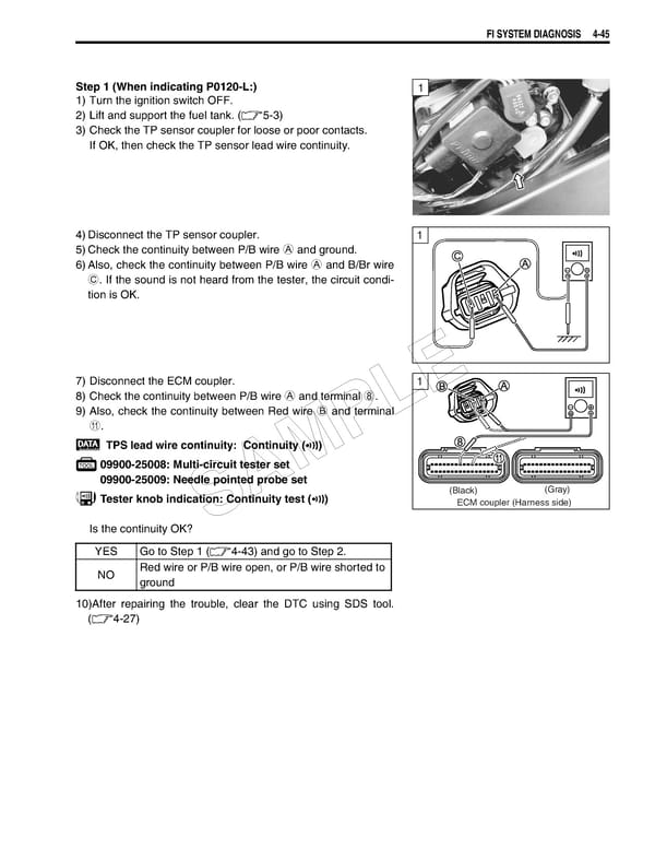
FI SYSTEM DIAGNOSIS 4-45 Step 1 (When indicating P0120-L:) 1 1) Turn the ignition switch OFF. 2) Lift and support the fuel tank. (5-3) 3) Check the TP sensor coupler for loose or poor contacts. If OK, then check the TP sensor lead wire continuity. 4)Disconnect the TP sensor coupler. 1 5)Check the continuity between P/B wire A and ground. 6)Also, check the continuity between P/B wire A and B/Br wire C. If the sound is not heard from the tester, the circuit condi- tion is OK. 7) Disconnect the ECM coupler. 1 8) Check the continuity between P/B wire A and terminal 8. E 9) Also, check the continuity between Red wire B and terminal L A. P TPS lead wire continuity: Continuity () 09900-25008: Multi-circuit tester set M 09900-25009: Needle pointed probe set A (Black) (Gray) Tester knob indication: Continuity test () ECM coupler (Harness side) Is the continuity OK? S YES Go to Step 1 (4-43) and go to Step 2. NO Red wire or P/B wire open, or P/B wire shorted to ground 10)After repairing the trouble, clear the DTC using SDS tool. (4-27)
 Suzuki GSXR 1000 K5 K6 Page 204 Page 206