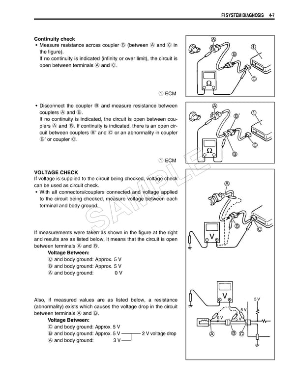
FI SYSTEM DIAGNOSIS 4-7 Continuity check • Measure resistance across coupler B (between A and C in the figure). If no continuity is indicated (infinity or over limit), the circuit is open between terminals A and C. 1 ECM • Disconnect the coupler B and measure resistance between couplers A and B. If no continuity is indicated, the circuit is open between cou- plers A and B. If continuity is indicated, there is an open cir- cuit between couplers B’ and C or an abnormality in coupler B’ or coupler C. 1 ECM VOLTAGE CHECK E If voltage is supplied to the circuit being checked, voltage check can be used as circuit check. L • With all connectors/couplers connected and voltage applied P to the circuit being checked, measure voltage between each terminal and body ground. AM If measurements were taken as shown in the figure at the right S and results are as listed below, it means that the circuit is open between terminals A and B. Voltage Between: C and body ground: Approx. 5 V B and body ground: Approx. 5 V A and body ground: 0 V Also, if measured values are as listed below, a resistance 5 V (abnormality) exists which causes the voltage drop in the circuit 5 V between terminals A and B. Voltage Between: 0 V 5 V C and body ground: Approx. 5 V B and body ground: Approx. 5 V 2 V voltage drop A and body ground: 3 V
 Suzuki GSXR 1000 K5 K6 Page 166 Page 168